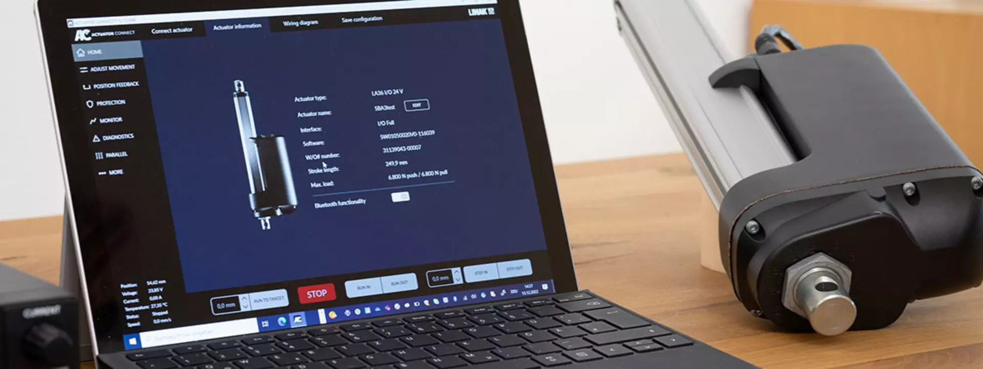
Occasionally things stop working and this leaves you with the task of identifying the root cause. The ’Diagnostics’ features in our Actuator Connect™ configurator can help you avoid downtime in your application and guide you through the troubleshooting of your electric I/O actuator.
Let Hunter guide you through the Diagnostics features of an I/O actuator, one of several options configurable in the Actuator Connect configurator for the LINAK® I/O interface.
Learn more about our I/O interface , or download a free version of the latest Actuator Connect configurator.
LINAK distinguishes between internal and external errors. If the actuator has detected an internal error and has stopped - try to repower the system or initialise the actuator. If the internal error cannot be solved, please contact your local LINAK office for further assistance. For external errors, you can find different remedies to solve a potential issue here.
Electric linear I/O™ actuators come with a transparent connector with integrated LED for fast diagnostics by simple visual inspection. This can be enabled as a software feature in the ‘Diagnostics’ option menu in Actuator Connect™.
The LED can show different colours depending on the actuator state and can be used to quickly determine whether the actuator is running as intended or shows a failure that needs to be looked at more closely.
When the actuator is fully operational, the LED will be green. If the colour of the LED changes (to either red or yellow), it indicates a system malfunction.
For applications where downtime is not an option, LINAK offers error codes as a digital output for easy troubleshooting.
During a 10 second time frame, you can read out error codes on the digital output. The actuator will send a number of pulses to your controller (PLC) depending on the error type – following the patterns in the table shown in the below video or on this troubleshooting page.
Error codes take up one of the digital outputs, which means that you can still use the other output for position feedback or endstop signals.
Did you know?
We understand the importance of uptime – and hence, an inoperative electric actuator must be fixed or replaced as quickly as possible. Therefore, we have developed a 3-step guide with explanations of the most fundamental reasons for the problems, and what you can do to fix them. It considers LED status - for fast diagnostics by simple visual inspection, error codes – sent directly to your controller/PLC, and our supporting PC configuration tool, Actuator Connect.