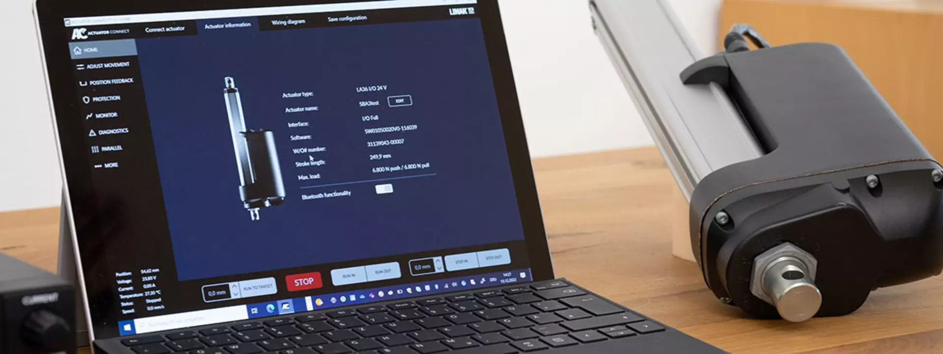
The ‘Adjust movement’ features in the Actuator Connect™ configurator offer more flexibility for LINAK® I/O™ actuators with various control options, virtual limits, and adjustable speed – allowing you to be completely in control of your linear movement behaviour.
Let Hunter guide you through the Adjust movement features of an I/O actuator, one of several options configurable in the Actuator Connect configurator for the I/O interface.
Learn more about our I/O interface , or download a free version of the latest Actuator Connect configurator.
Controlling an electric linear I/O actuator is based on an integrated controller or H-bridge that switches the polarity of the voltage to the DC motor. Here you can benefit from low-current switching, since a high digital signal of only a few mA will cause the actuator to run.
The integrated H-bridge opens a variety of control options from the PCB, such as speed and ramping.
The H-bridge has four switches, in this case transistors, that are connected to the power supply at the top and the bottom of the H-bridge. These transistors replace mechanical relays. The H-bridge controls the in-and-out movement of an actuator in a fairly simple way. When power is on – two of the transistors must be activated to make the current flow diagonally past the motor connection – making the motor run in one direction.
The I/O actuator can be controlled with an analogue signal. In this case, the input is variable and not just simply on or off. The analogue input signal can be used to control either position or speed.
Servo control is used to control the actuator position. This is done with an analogue input, such as 4-20 mA, which covers the entire actuator stroke length. This is especially relevant in applications where the actuator has to move to several target positions during normal operation.
Proportional control is similar to servo, but instead of controlling the piston position, the analogue signal controls the speed and direction of the actuator. A common type of proportional control is the joystick, where the middle position is neutral and moving it backwards or forwards will move the actuator in equivalent direction.
Predefined positions are useful, if you want to move to the exact same position every time. This can for instance be controlled by push buttons or entered as a command on your PLC (Programmable Logic Controller). The digital input signal should remain high, until the target position has been reached, but it will not move beyond that point.
Learning mode allows the actuator to learn a new endstop. The learning is based on predefined zones along the stroke length and a current limit to trigger the new endstop – like an obstruction. In some cases, it can be a good idea to add a ‘step back’ after meeting an obstruction – this allows you to set a new endstop slightly away from the mechanical block, which will potentially extend the service life of the actuator and provide smoother movement.
It is also possible to set speed for the actuator in learn mode – in case you would like it to run slower when learning an obstruction.
Learn mode can be performed directly in Actuator Connect™ or by shortening the red and black wires.
Did you know?
From the Home menu in Actuator Connect, the Wiring diagram tab allows you to see the actual wiring diagram of the connected actuator.
The wiring diagram is important, because the I/O actuator offers various input and output wiring options with many opportunities to control and adjust the actuator.
The functionalities of these inputs and outputs can be customised directly in Actuator Connect, and the wiring diagram will be updated accordingly.